
I’ve wanted a lathe for years, something to make simple bushings, spacers, etc. But I could just not justify spending the price of a brand new one. So, naturally, I made the brilliant decision to buy a clapped out, used one and then spend far more money than a new one would have cost anyways.
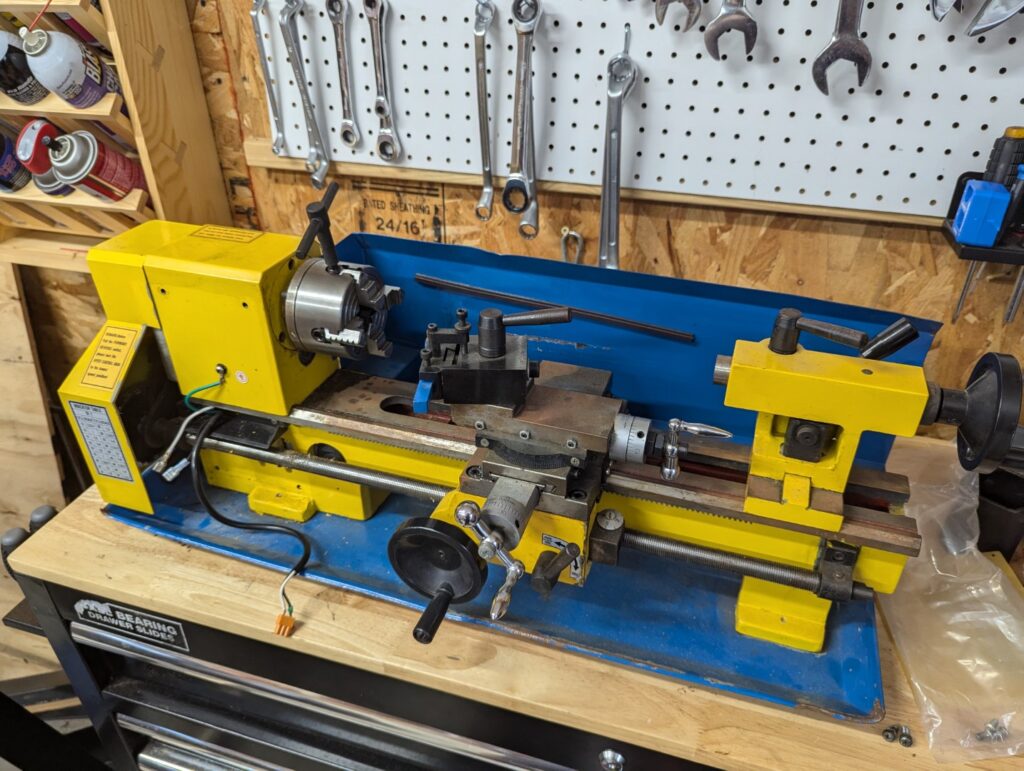
It’s a pretty standard 7×10 lathe, sold by Cummins, but it’s the standard Harbor Freight/Chinese mini-lathe.
The lathe felt in pretty good shape, but the electronics were not working. Not positive if it was the motor itself or the control board, some day I may try to repair it, but for today, we just upgrade. First though, let’s tear it down!
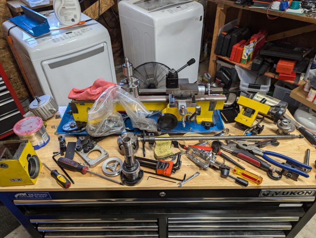
One of the biggest upgrades for these lathes is a set of tapered roller bearings in the headstock. The bearings used from the factory are typical ball bearings, which allow some deflection, reducing precision. Now I don’t plan on making much that needs more than one decimal point of accuracy, but still, it’ll be nice to have!
I removed the old bearings and prepared to press the new one onto the shaft of the headstock. Having a hydraulic/bearing press would make this job really simple, but I don’t have one of those.
…or do I?
Some 2x6s, a hydraulic pump jack and a lot of prayers made to the strength of wood! But it worked beautifully and didn’t seem at risk of breaking at any point.
I reassembled the headstock, replacing the plastic transfer gears with metal ones. Next up, let’s settle the motor.
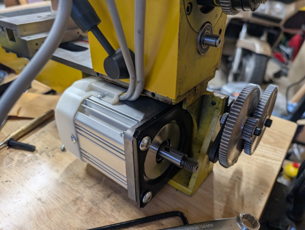
The motor is a “servo” motor, and includes a nice speed controller. Mounted to a simple right-angle 70mm stepper motor mount and bolted to the front of the lathe. Getting power from the motor to the headstock needed some new belts and pulleys, and once they arrived I realized I’d need to keep the belt tensioned as well, so off to CAD we go!
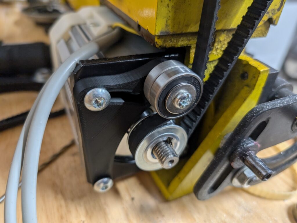
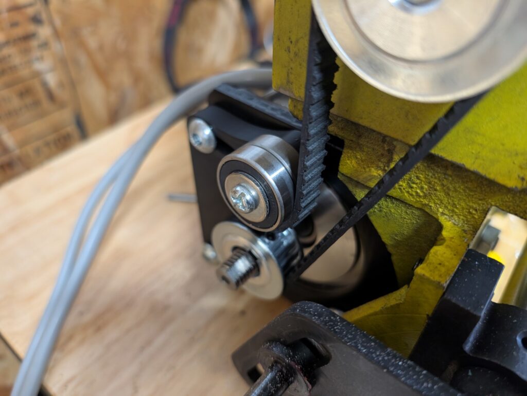
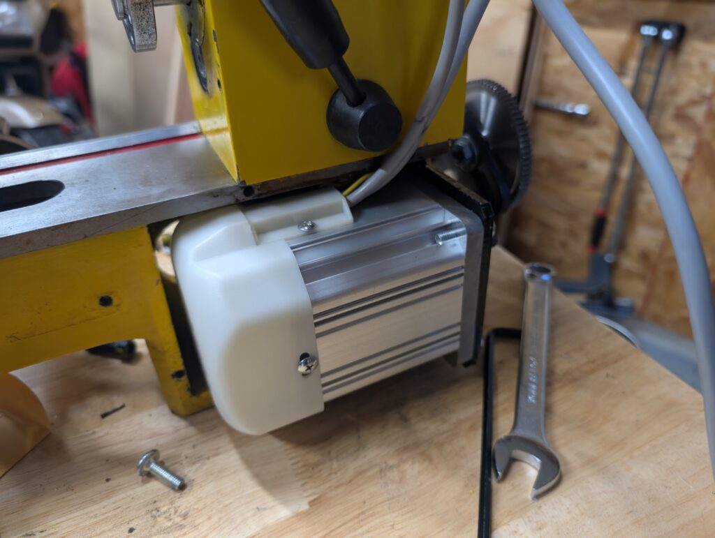
The tensioner is 3d printed, the actual rollers are just simple ball bearings. This setup works beautifully and transfers power well without any issues of slipping or binding. That said, I don’t know how much I trust the 3d printed plastic long term as a material, so I’ve ordered a metal version of the tensioner bracket from JLC CNC! Will get an update once it’s here!
With all that completed, the lathe was mostly ready to go! I installed a quick-change-tool-post, made sure everything was cleaned and lightly greased, and bought some cheap aluminum tube to make some test cuts with.
And there it is! At least up to this point. I recognize the measurement setup above isn’t perfect, but it’s a start!
I still need to work on reinstalling gear train at the back of the headstock that transfers power to the leadscrew/change gear train. With the change to the tapered roller bearings and the new (slightly larger) pulleys for the motor the change gear train will need to be pushed out ~5-10mm or so. I plan to 3d print a spacer to go behind it, but will need to work on the alignment of everything else.